PRODUCT DESCRIPTION
Manufacturers and users of electric vehicles are converting their DC motors to an AC induction motor as more advantages lean towards it than with DC motors. An AC motor is superior in terms of product life, efficiency, and torque generation. Navitas has various DC to AC Conversion kits and they come in different part combinations curated to supplement compatibility demands depending on the vehicle model, stock controller, and throttle type.
This product is one of the DC to AC Conversion Kits that Navitas offers. It is composed of a controller, an On-The-Fly (OTF) Programmer, a motor, a mounting kit, and cables. It is also only compatible with CLUB CAR vehicles utilizing Curtis 1510/1515 controllers.
The Navitas CLUB CAR DC to AC conversion kit can now be purchased in Cloud Electric, your one-stop shop for all your electric component needs and one of the leading distributors in North America. Our store takes pride in the service we provide such as reliable product information, the lowest possible prices, and shipping speed. The most in-demand products necessary for industrial vehicles ranging from boom trucks to golf carts are also available in the store.
Compatible Vehicle:
The kit is designed only for the following vehicles with Curtis 1510/1515 controller:
CLUB CAR IQ
CLUB CAR Precedent
CLUB CAR Onward
CLUB CAR Excel
CLUB CAR DS
Kit Inclusions:
TAC2 Controller (48V, 600A)
AC Induction Motor (4kW)
On-The-Fly Programmer
Cables
Mounting Kit
TAC2 Controller:
The TAC2 controller is a power MOSFET technology that is fully-programmable allowing flexible motor control. This controller has an output capability of up to 600A and battery voltage of 48-72V. This kit is specifically equipped with a 48V, 600A TAC2 controller.
Regenerative braking, speed limiting, and anti-rollback protection are some of the key features both controllers have. It can also communicate with other bluetooth, RS232, and CAN Bus-enabled devices allowing users to virtually change the settings of the vehicle.
Features of the TAC2 Controllers:
Capable of recapturing kinetic energy through regenerative braking
A voltage-controlled power MOSFET device
Allows safety through speed-limiting
Sensor input
Controller Specification:
|
TAC2 Controller
|
|
Compatible Motor
|
AC Induction Motor
|
|
Available Output
|
600A Model
|
|
Battery Voltage
|
48 V
|
Controller Information:
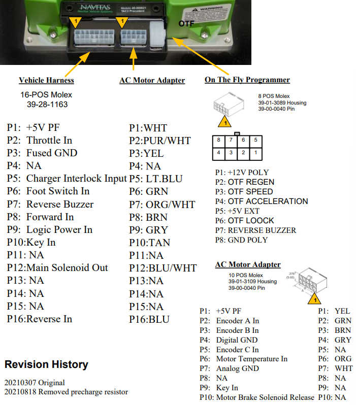
Wiring Diagram:

AC Induction Motor
The AC motor equipped in the Navitas CLUB CAR DC to AC conversion kit is a 10-spline motor with a power rating of 4kW. This motor is a premium AC induction motor built with high-quality material and has a reliable construction capable of providing high speed and torque.
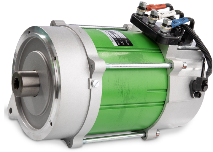
Motor Specification
|
Rated Power
|
4kW Motor
|
|
Splines
|
10 Splines
|
|
Motor Frequency (Hz)
|
123
|
|
Rated AC Voltage (V)
|
34
|
|
Rated Current (A)
|
91
|
|
Rated Speed (RPM)
|
3600
|
|
Speed (RPM)
|
0~6800
|
|
Ingress Protection
|
IP44
|
On-The-Fly Programmer
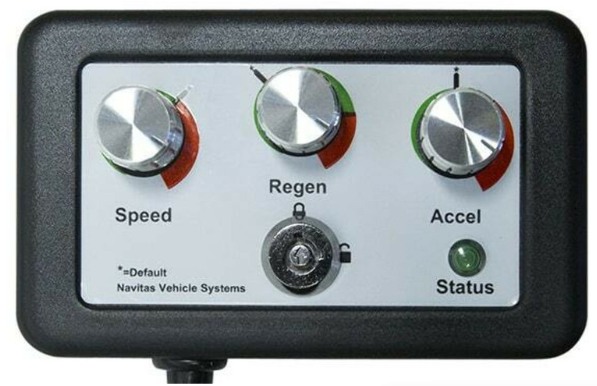
An OTF Programmer uses a programming style that allows live coding during run time allowing the driver to control the vehicle while operating.
Parts of the On-The-Fly Programmer:
The OTF programmer has 5 parts—3 switch knobs, a key lock, and an LED light indicator.
Switches: The switch knobs are for Speed, Regen, and Acceleration.
The SPEED switch functions as a speed and range controller. When limiting the speed to a lower rate, the vehicle will have a longer runtime.
The REGEN switch allows braking control both for safety and its recharging capabilities.
The ACCEL switch allows acceleration control to ensure that the vehicle is safe from sudden unintended acceleration.
Key Lock: A safety feature that ensures that the car rejects input unless unlocked.
STATUS LED Light: Indicates the condition of the vehicle providing system diagnostics to alert the driver.
Cables
Motor Sensor Cable
The Motor Sensor Cable is responsible for data transmission from the sensor to the control unit. The cable included in the kit transmits temperature and speed of the motor.
Dimensions (inch):

AC Motor Phase Cable
This motor cable is used for the ‘W’ terminal. The existing cables A1 and A2 are for terminals U and V, respectively.
Dimensions (inch):

Mounting Kit
The provided aluminum mounting plate in the Navitas conversion kit is designed to fit right to the location of the stock controller.

Hardware
The kit comes with the necessary screws needed for installation.

INSTALLATION GUIDE
Controller and On-The-Fly Programmer
Take out the stock controller. To do this, remove the cover to access its location.
Place the Navitas mounting plate and secure it using the provided holes. The screws that fit these holes are included in the mounting kit.
Remove F1 and F2 cables of the DC motor.
On the back portion of the TAC2 controller, apply an adequate amount of thermal grease in order to seal the heatsink of both the cart and the controller allowing the heat to transfer from the controller. The controller is likely to run cooler when this method is applied.
Place the controller on the mounting plate.
Retrieve the run/tow switch from the stock housing and hook it up with the provided mounting plate in the kit, then place it beside the controller.
It is recommended to upgrade the solenoid as the stock solenoid may not be able to handle the demand.
Install the On-The-Fly programmer on the dashboard.
Plug the harnesses and secure the wiring according to the module provided.
Motor
Remove the DC motor by removing the cover plate. Carefully remove the positive and negative of the battery, take the bolts out, and lift the motor out from the compartment.
Gently place the AC induction motor and secure it with bolts.
Connect the motor wires.
Use insulator caps, if provided, to avoid electrical leaks and protect the motor.
Place the cover back on the vehicle.
Test the vehicle.
NAVITAS BLUETOOTH APP GUIDE
Install the controller to the cart then turn the vehicle on. Specific carts may require turning the Run/Tow switch or the Key Lock ON.
Open the app and connect the controller through Bluetooth. The controller nearest to the user will show up on the list first. Click the controller to view its status.
To adjust settings, go to Settings and input the desired data then press Save.
The Settings page contains the following sections:
Speedometer Settings
Speed Limits
Input Thresholds
Advanced Options
Vehicle Direction
Off-Road Performance
Vehicle Information
To see the real-time vehicle activity, go to Settings.
Under the Vehicle Information section, toggle the buttons of the parameters you want to view then run the data log to see graphs of the chosen parameters.
To run the data log, press the Start button on the upper right corner of the screen.
The generated data cannot be saved. It can only be shared to the Navitas team by clicking the Cloud button beside the Start/Stop button.
To view the state of the vehicle, go to the Dashboard of the app.
|
ICON
|
FUNCTIONS
|
ICON
|
FUNCTIONS
|
|

|
This icon indicates errors, faults, and warning signs regarding the state of the vehicle. When clicked, the user has the option to email the warning to the dealer.
|

|
This button assists you to remotely lock or unlock the vehicle even with key placed.
|
|
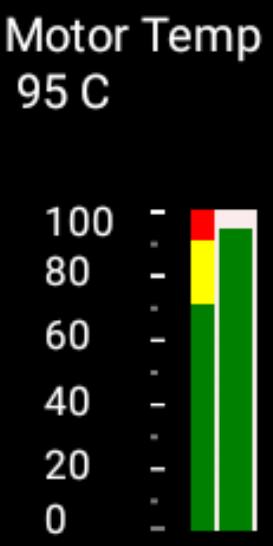
|
Measures the temperature of the motor indicating how hard the vehicle is working.
|

|
Measures and indicates the charge of the battery.
|
|

|
This indicates the direction that the car is travelling. The symbols are F, N, and R symbolising Forward, Neutral, and Reverse, respectively.
|
|
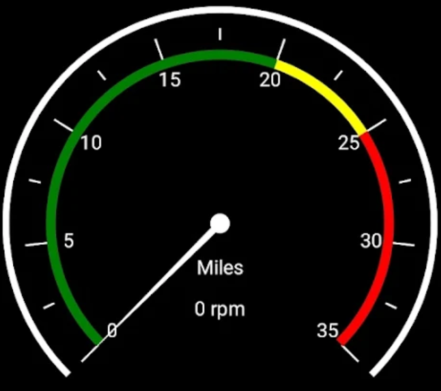
With the correct indicated tire size and rear axle ratio on the Settings page, the speed of the vehicle will be reported directly from the vehicle.
|
|

|
This shows whether the key is on the vehicle and greyed out, otherwise.
|

|
These Green Words indicate the status of the vehicle.
|


